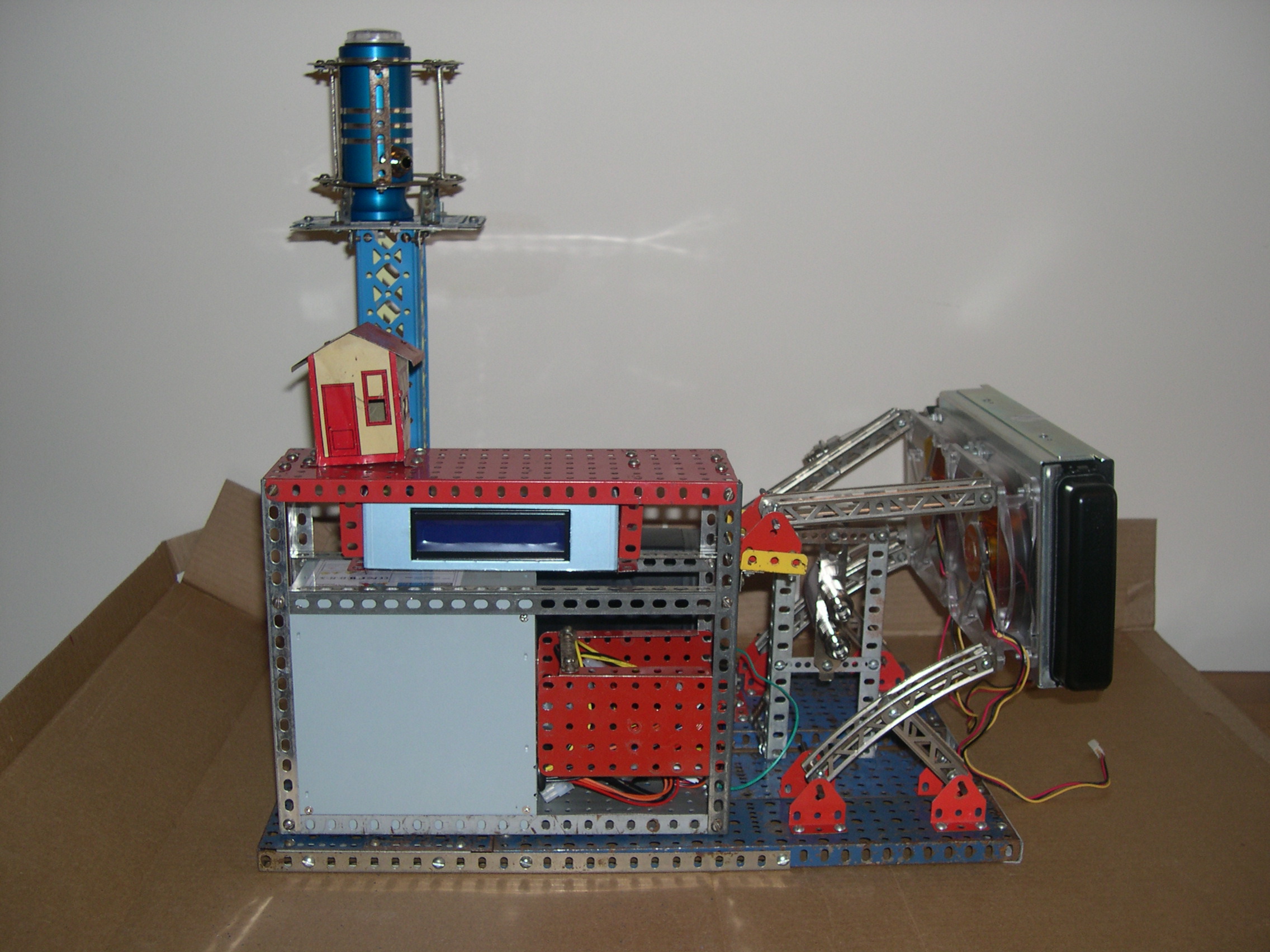
This is probably the final design, but not completed by a long shot. The grey box mounted on the lower left is a power supply. This will be changed for a nicer one, probably modular. The LCD screen above it is the screen for the Asetek pump, which was DOA. After reading more about it in forums (afterwards, of course, duh!), I will ditch that and get something else. After almost a week, still waiting on Asetek to reply. From what I read in the forums, I'm not too hopeful.

The little operations shack at upper left is the only thing in there just for effect. Everything else is structural.

Neither the wire management or the plumbing has been done.
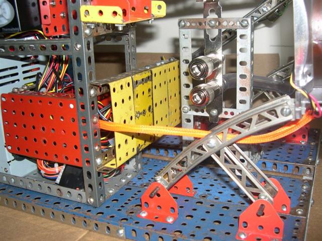
Detail of the mounting frames for the radiator. They actually connect to the fans. In the middle, you can kinda make out the Koolance quick disconnects for the hoses that will come from the PC.

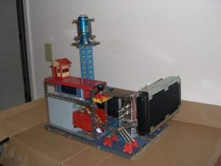
Right side view.

The wiring show the need for management, here.

Rear view with Aserek pump. At the time of this photo I didnt' know it was dead.

Pretty good idea of the layout, here. Red power supply cage at right rear, to the left of that you can see the quick disconnects for the PC hoses, and the radiator with the twin 120mm Akasa Amber series fans. Lower right is the reservoir tower with the pump to the left of that. The power is in on the front of the unit and the plumbing all along the rear. The only power that goes towards the rear is for the pump. The only water that goes towards the front is the outlets for the PC.

The tower didn't really need to be that tall, but I did want it to be the highest thing in the system so the air will collect there. The feed from the PC will go to the low side of the radiator, from the top of the radiator to the top of the reservoir, from the bottom of the reservoir to the pump, and then back to the PC.

Looks tall and skinny here. I think the reason it looks like it is out of alignment is either the cardboard, or the wide angle lens making it look that way. It's actually pretty straight.

I should have removed this shot, but I'm too lazy.

This gives a little better view of how the sides are separated. It'll be even clearer in the finished system. All electrical wiring will be sleeved red (OK, so it's orange, but they advertised it as red, so I'm going to call it that. Allow me my delusions), the data (temp sensors in this case) will be green, and the water blue.

Close up of the radiator end.

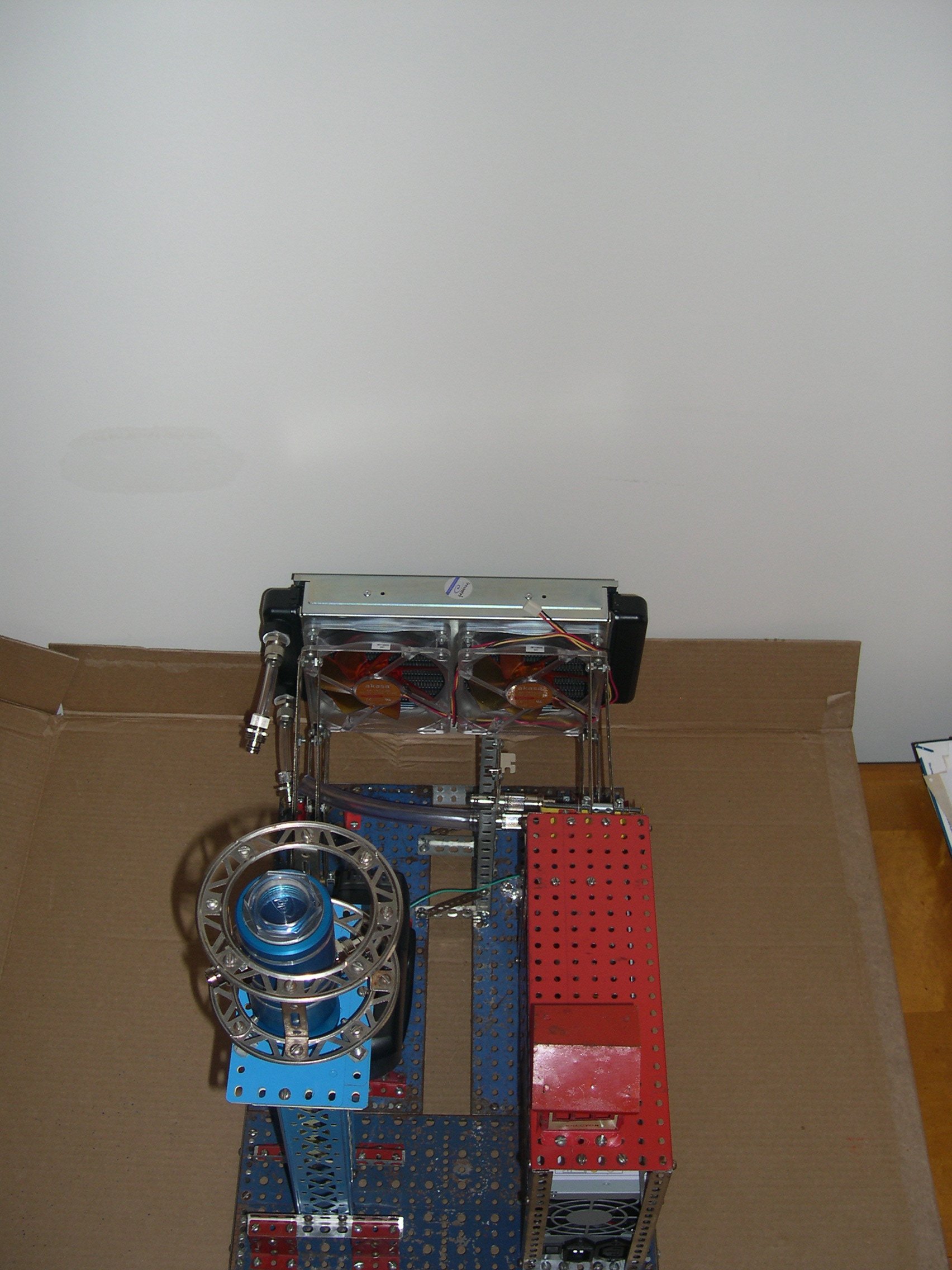
Straight down shot.

Straight down from the other end.

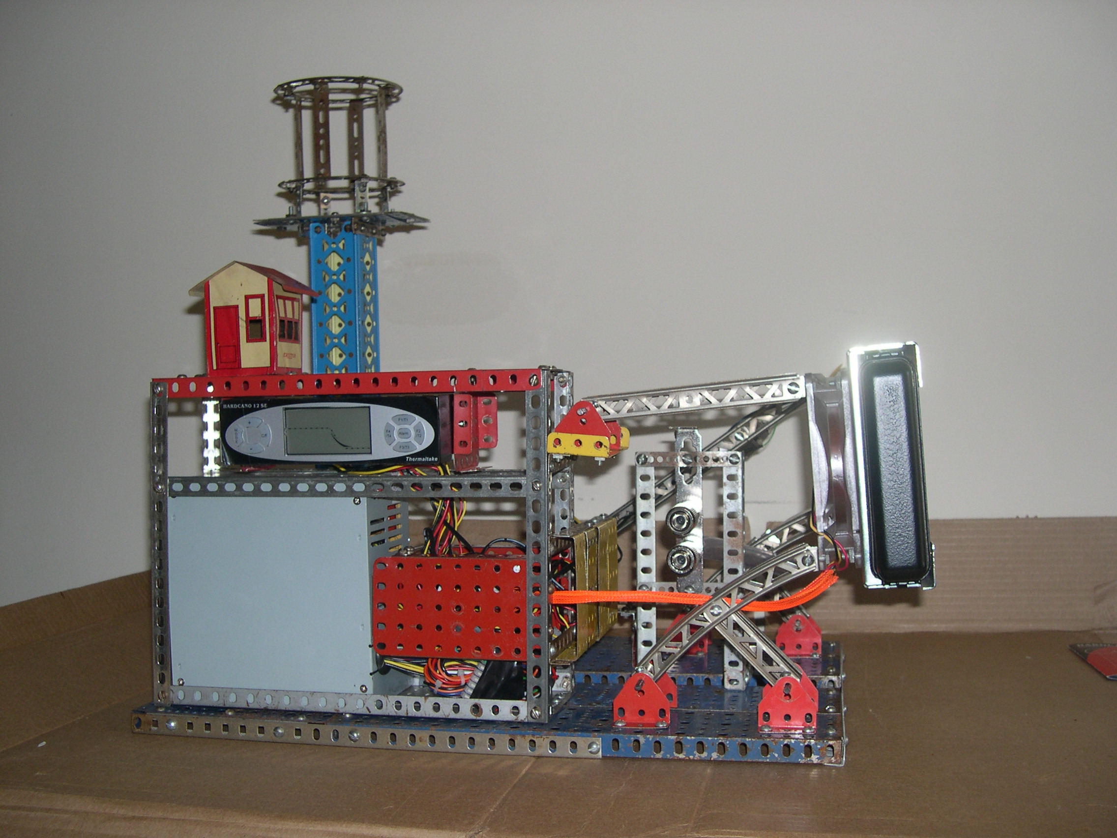
A little work has happened, now. The Asetek pump and LCD have been removed. Added a Thermaltake Hardcano fan controller in it's place.

Sleeved the wires from the radiator fans. Also got the operations shack to set level.

I added a channel (yellow in center) for the wires and temp sensors to run through to the back side.

And there's where the channel comes out. Right by the bracket of the dead Asetek.

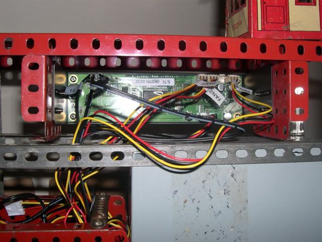
Rear of the Hardcano. 3 sensor/fan pairs wired. One for each fan (one sensor will go inside the radiator fins, the other I'll experiment). The third is for the power supply. I cut the fan leads and spliced in a connector. The temp sensor is tapped to one of the heat sinks. Funny, I couldn't hear the Akasa fans over the PS noise. But now, those Akasa's sound loud, even at low power.
