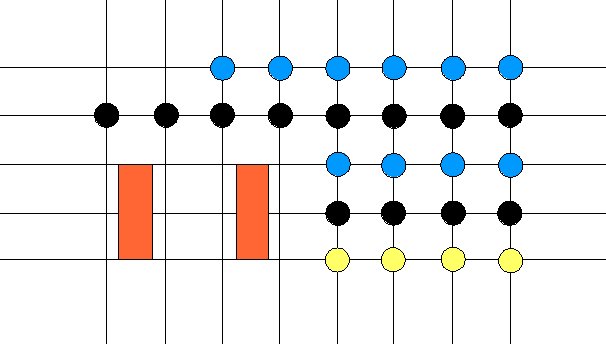
First layout drawing.

Same thing cleaned up and saved as an image.

From left to right, the color the item matches in the previous diagram. 1. Momentary switch - Yellow 2. Green indicator LED - Blue 3. Micro-toggle switch - Black 4. Bat handle red lighted - Red

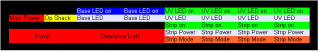
A layout showing the components by function.
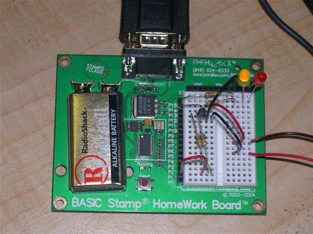
Working on a Basic Stamp 2 circuit to set the LED light stick operation mode. When the light sticks power up they are in a mode that cycles through all the modes. I want most (or all) of them to but just on solid. That means pressing the momentary switch 7 times. 5 sets of lights means 35 presses each time it cranks up. This circuit, along with the program to control it, will "press" the button 7 times in 1/3 second, all 5 sets at the same time. It also blinks the red LED in a cool pattern that makes it just like a clearance light (on 1/4s, off 1/4s, on 1.5s off 2.5s). I'll also be able to program it to do light patterns in other places. The resistor and LED on the top is the clearance light circuit. The other two resistors, transistor and jumpers are for the UV stick control circuit (1 set)

Here I added another LED circuit for the operations shack. This LED flickers off randomly about once a minuite to simulate a bulb going bad. I'll add 4 more control circuits for the light sticks and then some controls for another lighting idea I have,
